---
title: "Control Circuit description"
id: "control-circuit-description"
project: "Clean Power VFD User Guide"
url: "https://smartd.clickhelp.co/articles/clean-power-vfd-publication/control-circuit-description"
updated: 2026-10-29T18:46:20Z
---
# Control Circuit description
[Home](/articles/clean-power-vfd-publication/home) » [Installing the VFD](/articles/clean-power-vfd-publication/installing-the-vfd) » [Electrical Installation](/articles/clean-power-vfd-publication/electrical-installation) » Control Circuit description
* * *

**Digital Input Signal Integrity:**
Incorrect digital input states can lead to unintended drive behavior.
Improper wiring or excessive input voltage may cause the VFD to misinterpret input signals (0/1 logic state). This can result in:
* Unexpected motor start when a stop command is intended
* Failure to start when a run command is issued
* Incorrect rotation direction selection
**Instructions:**
* Verify wiring against the control diagram before commissioning
* Confirm logic configuration (NO/NC) matches the application intent
* Measure input voltage levels to ensure they remain within specification
* Validate input status via HMI or mobile app before enabling motor operation
Failure to follow these instructions may result in unintended motor operation.
* * *
## Control Circuit Connection Diagram and functions
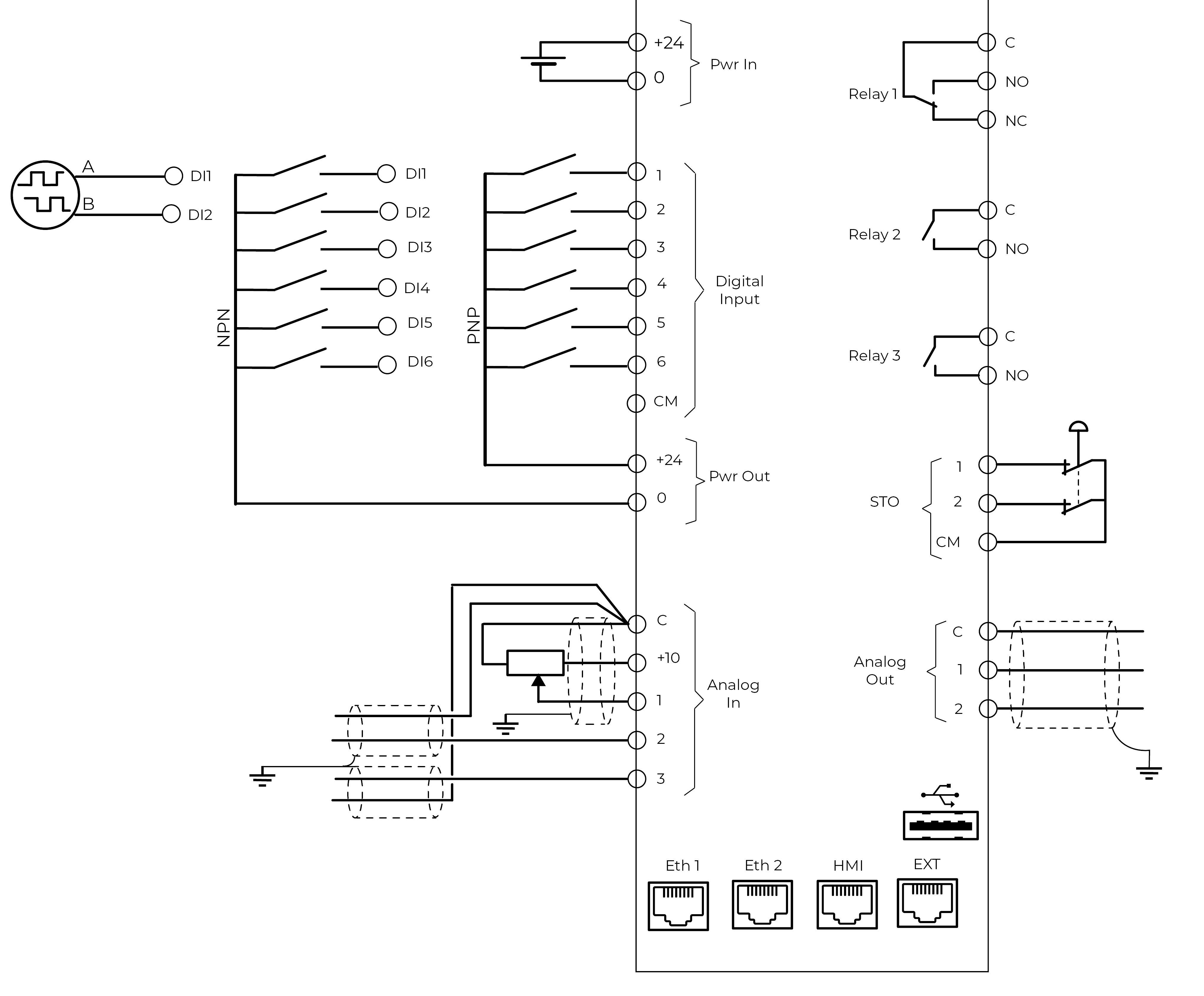
The illustration below shows the detailed layout of control wiring terminals.
|  | **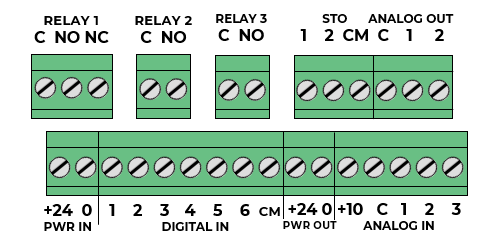**
**Control terminal blocks Features:**
- Screw type: M3
- Tightening torque: 0,5 Nm / 4.5 in-lbs.
- Conductor type: copper only
- Conductor stripping length: 7 mm / 0.28 in
- Solid conductor cross-section: 0.05mm² ... 2,5 mm² / AWG 30 ...12
- Flexible conductor cross-section with Ferrule: 0,05 mm² ... 2,5 mm² / AWG 30 ... 12
|
| --- | --- |
### 24VDC power in
The 24VDC auxiliary supply will power the Clean Power VFD control board without line power, allowing the control board, communications, and the HMI to continue to operate.
It is recommended that you connect a 24VDC to this auxiliary power input, as this allows you to export logs for support and troubleshooting purposes if needed.
If a 24VDC is used while commissioning the Clean Power VFD and line power is absent, the Clean Power VFD will be in the under-voltage alarm state.
Ensure to use a DC power supply that meets the following specifications:
* Nominal operating voltage: 24 VDC
* Minimum continuous operating voltage: 19.2 VDC
* Maximum continuous operating voltage: 28.8 VDC
* Maximum power supply requirement at 24V: 50 W
* Recommended protection fuse: 4A - 50 VDC
|  | To ensure proper operation and avoid potential issues like ground loops, noise interference, and malfunctions, do not connect the 24VDC common terminal to the ground.
Read carefully and apply the recommendations from the user guide chapter [Grounding](/articles/clean-power-vfd-publication/grounding) |
| --- | --- |
### 24VDC power out
This power is used to energize the digital inputs or to energize some sensors.
Ensure that the maximum current level, as defined in the following specifications, is respected.
* Nominal operating voltage: 24 VDC
* Minimum continuous operating voltage: 19.2 VDC
* Maximum continuous operating voltage: 28.8 VDC
* Maximum output current at 24V: 100mA
* Recommended protection fuse: 4A - 50 VDC
### Digital input terminals
| Marking | Name | Default Operation |
| --- | --- | --- |
| 1 | Digital input 1 | User-settable. It can be used for an encoder, phase A. Default setting: unused |
| 2 | Digital input 2 | User-settable. It can be used for an encoder, phase B. Default setting: unused |
| 3 | Digital input 3 | Run forward |
| 4 | Digital input 4 | Run Reverse |
| 5 | Digital input 5 | Stop |
| 6 | Digital input 6 | Select reference speed between preset 1 and analog input 1 |
| +24 | Common terminal for digital inputs | |
The user can assign the digital inputs to various functions such as:
* Rotation direction,
* Stop,
* Selection of the speed setpoint source
* Selection of the local/remote control mode
Check the complete list in the chapter "[Digital Input Settings](/articles/clean-power-vfd-publication/digital-inputs-setting)"
Their logic operation is also user-settable; the choices are between:
* rising or falling edge
* level high or low
Last, a debounce delay is also user-settable to avoid false input triggering. This timer's range is 0 to 5000 ms; its default value is 200 ms.
### Analog Input Terminals
| Marking | Name | Default Operation |
| --- | --- | --- |
| 1 | Analog input 1 | Speed reference (Hz) - preset to be used as potentiometer input |
| 2 | Analog input 2 | un-assigned |
| 3 | Analog input 3 | un-assigned |
| +10V | Reference power supply | 10VDC - 10 mA max |
| C | Common terminal for Analog inputs | |
The user can assign analog inputs from AI1 to AI3 to various functions and electrical signals.
Available choices for the functions are
* Speed (frequency - Hz) setpoint
* Velocity (RPM) setpoint
* PTC motor thermal sensor
* Unused.
Check the complete list in the chapter " [Analog input settings](/articles/clean-power-vfd-publication/analog-inputs-setting)"
The signal that can be wired to the Analog input can be either
* 0..10VDC,
* 4..20mA,
* PTC.
### Relay output terminals
Relay 1: SPDT
| Marking | Name | Default Operation |
| --- | --- | --- |
| C | Common of the contacts | Relay 1 (SPDT) is assigned by default to be the alarm relay.
The relay is energized when there is no alarm present (C and NO connected).
The relay is de-energized when there is an alarm or a loss of power supply (C and NC connected) |
| NO | Normally opened contact |
| NC | Normally closed contact |
Relays 2 and 3: NO
| Marking | Name | Default Operation |
| --- | --- | --- |
| C | Common of the contact | Relay 2 (NO) is the factory default setting to be closed when the drive is in the state “ready to run”.
Relay 3 (NO) is the factory default setting to be closed when the drive is in the state of “running”. |
| NO | Normally opened contact |
The operation of the 3 independent relay outputs of the Clean Power VFD can be set by the user.
The settings are described in the chapter " [Relays setting](/articles/clean-power-vfd-publication/digital-outputs-setting)"
### Relays protection
Always protect relay outputs from inductive load damage, using an appropriate external protective circuit or device.
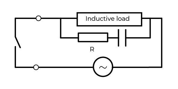
C: a capacitor from 0.1 to 1 μF.
R: resistor of approximately the same resistance value as the load.
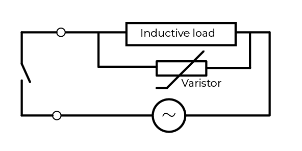
In applications where the inductive load is switched on and off frequently and/or rapidly, ensure that the continuous energy rating (J) of the varistor exceeds the peak load energy by 20 % or more.
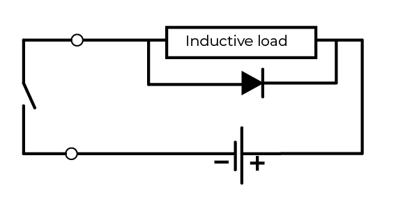
Use a diode with the following ratings:
Reverse withstand voltage: power voltage of the load circuit x 10.
Forward current: more than the load current.
### Analog Output Terminals
| Marking | Name | Default Operation |
| --- | --- | --- |
| 1 | Analog output 1 | Analog Output 1 is factory-preset to be assigned to the motor frequency. The preset signal is 0..10VDC |
| 2 | Analog output 2 | Analog Out 2 is factory-preset to be assigned to the motor current I total. The preset signal is 0..10VDC |
| C | Common terminal for Analog outputs | |
The user can assign analog outputs 1 and 2 to various functions and electrical signals.
Available choices for the functions are
* Motor Current
* Motor Frequency
* Motor Torque
* Motor Power
* Unused.
Check the complete list in the chapter "[Analog outputs setting](/articles/clean-power-vfd-publication/analog-outputs-setting)"
The signal that is delivered by the analog output can be either
* 0..10VDC
* 0..20mA
* 4..20mA.
Selection and scaling are made using the mobile App.
### Torque Deactivation terminals
The Torque Deactivation enabling terminals are positive logic input only.
The user is responsible for ensuring the complete system is safe and designed correctly according to the relevant safety standards.
If the Torque Deactivation function is not required, the terminals STO1 and STO2 must remain connected to +24VDC.
| Marking | Name | Default settings |
| --- | --- | --- |
| STO1 | Torque Deactivation - input 1 | Open: Torque Deactivation is enabled, and the Clean Power VFD output is de-energized.
Closed: Torque Deactivation is disabled, and the Clean Power VFD is in normal operation
Note: Remove the jumper between STO1 and +24V using the torque deactivation input.
The length of the wire should not exceed 30 m (98.4 ft). |
| STO2 | Torque Deactivation - input 2 | Open: Torque Deactivation is enabled, and the Clean Power VFD output is de-energized.
Closed: Torque Deactivation is disabled, and the Clean Power VFD is in normal operation
Note: Remove the jumper between STO1 and +24V using the torque deactivation input.
The length of the wire should not exceed 30 m (98.4 ft). |
| +24 / CM | Torque Deactivation supply connection | Delivers +24V for the Torque Deactivation inputs when the VFD is configured in Source logic mode.
Refer to the [digital input logic connection](/articles/clean-power-vfd-publication/digital-input-logic-connection) section to wire the Torque Deactivation terminals correctly |