Home » Installing the VFD » Electrical Installation » Control Circuit description » Digital input Logic Connection
 Learn about sinking and sourcing
Sourcing / Sinking
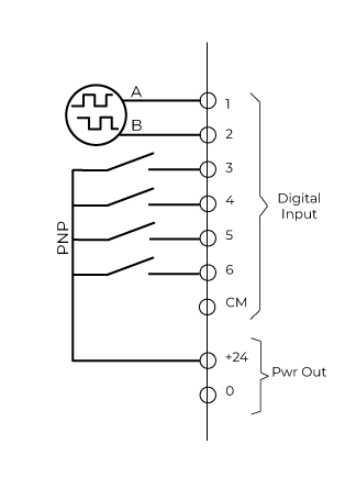
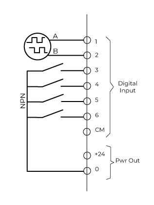
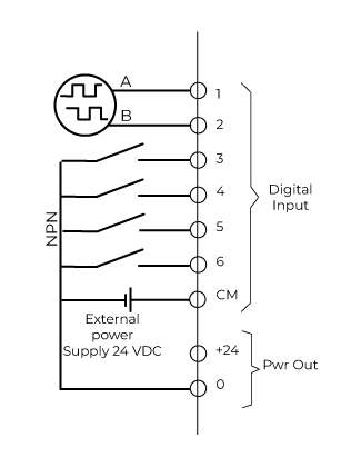
Digital inputs DI1 to DI6 can be wired either in Source (PNP) or Sink (NPN) mode.
Selection is made by settings in the software.
By default, the digital inputs are set to be wired in Source (PNP) mode.
Note that you can not mix source and sink wiring modes, all inputs from DI1 to DI6 must be wired in the same mode.
Wiring in Source mode

|
The terminal CM, within the Digital Input group, is named +24 on the former generation of Clean Power VFD. |
Wiring in Sink mode - use of the internal power supply
|
|
The terminal CM, within the Digital Input group, is named +24 on the former generation of Clean Power VFD. |
Wiring in Sink mode - use of an external power supply
|
|
The terminal CM, within the Digital Input group, is named +24 on the former generation of Clean Power VFD. |
Torque Deactivation wiring
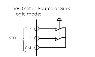
Terminals STO1 and STO2 must always be energized by +24VDC.
If you don't use the Torque deactivation function, do not remove the short-circuit already wired on the delivered VFD