Home » List and Details of alarms and protections » Motor overheating protection (code: 14)
| Parameter | Setting range | Default value |
|---|---|---|
| Alarm enable | Enabled / Disabled | Enabled if an analog input has been configured as PTC sensor. Else: Disabled |
| Trigger condition | Not user settable | The PTC sensor’s resistance sharply spikes because the motor temperature exceeds a critical threshold |
| Trigger delay | 0 to 10 s | 0.2 s |
| Trigger action | Not user settable | VFD is locked out, output is de-energized |
| Reset condition | Not user settable | The motor temperature cools down enough to let the PTC resistance decrease lower than the reset value. |
| Reset delay | Not user settable | Immediate upon reset conditions are true |
| Alarm persistence after power cycle | Enabled / disabled | Enabled |
| Additional settings / behavior | - | - |
Introduction:
Overtemperature poses a significant risk to electric motors.
If not adequately monitored and addressed, it can lead to catastrophic consequences, including the destruction of motor insulation and even motor failure.
To mitigate this risk, many motors incorporate thermal sensors within their windings.
PTC sensors stand out among the various sensors used for this purpose.
What Are PTC Sensors?
- PTC sensors are Positive Temperature Coefficient devices.
- Their resistance increases significantly with rising temperature.
- When embedded in motor windings, they act as reliable temperature monitors.
How PTC Sensors Work:
- At normal operating temperatures, PTC sensors exhibit low resistance. (3)
- However, as the motor temperature rises due to increased load or other factors, the resistance of the PTC sensor starts climbing.
- Once the temperature surpasses a critical threshold, the PTC sensor’s resistance sharply spikes (1)
- Exceeding its maximum resistance (2) allows to detect if a PTC is disconnected
- A resistance lower than its minimal resistance allows to detect a short-circuited PTC
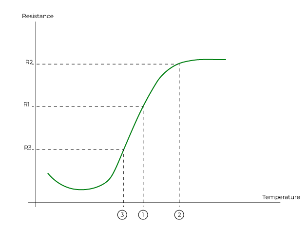
The Clean Power VFD can be connected to the PTC sensors of the motor to achieve thermal protection, using one of its analog inputs.
Implement motor thermal protection (Motor Overtemperature alarm)
When the user wants to enable the motor thermal protection using a windings-embedded thermal sensor, the first action he’ll have to do is to configure an input to be wired and configured.
The choice can be made between
- Analog input 1
- Analog input 2
- Analog input 3
If an analog input has been configured as a PTC temperature sensor, then the thermal protection function of the motor is enabled by default.
This thermal protection function of the motor can be enabled/disabled by the user.
The user can set a time delay to prevent unwanted motor overtemperature alarms, acting as a filter. This delay is settable between 0.0 and 10.0 s, its default value is 0.2 s.
Memory
A memory behavior can be set as enabled or disabled by the user during the VFD settings phase ( but cannot be changed when the VFD is in operation).
Default value: Enabled.
- When the Motor_overtemperature_memory is enabled, if the VFD is powered off and on after an overtemperature alarm, and before the sensor resistance crosses down the reset threshold, then the VFD remains in alarm status and can not restart the motor.
When the resistance value crosses the reset threshold, then the alarm can be reset. - When the Motor_overtemperature_memory is disabled, if the VFD is powered off and on after an overtemperature alarm, then the VFD returns to a ready status if the sensor resistance is lower than the overtemperature trigger point.
Without a power cycle, the VFD returns to a ready status when the sensor resistance decreases to a lower value than the reset threshold of the sensor curve.
These settings are accessible during the VFD settings, not during the VFD operation.
After addressing the issue, the alarm resets automatically, and the VFD can restart the system.