Home » Functions and parameters » Inputs and outputs » I/O's preset configuration » 2-wires, 3-wires, preset I/Os assignment
The following sections explain the two primary methods for wiring the VFD control inputs and outputs, commonly referred to as 2-wire and 3-wire configurations.
These two options provide flexibility in how the VFD is controlled, whether using a maintained contact, such as a PLC output, or separate momentary pushbuttons, such as a dedicated Start/Stop station.
The following sections describe each control mode, the default I/O assignments, and their operation.

IMPORTANT — CONTROL SOURCE
The Start, Stop, and Direction commands assigned to the digital inputs are control commands from the digital I/O control source.
These commands control the motor only when the corresponding I/O source is the active control source.
For example, if the VFD is operating in Local control, a Start or Stop command received from a digital input does not control the motor. This is particularly important in 3-wire control, where a physically wired Stop pushbutton does not stop the motor while Local control is active.
Refer to Control Source for information about Local and Remote control-source selection.
NOT A SAFETY FUNCTION
The Start and Stop commands described in this topic are operational control functions. They do not replace an emergency-stop circuit, Safe Torque Off (STO), or an energy-isolation procedure.
2-wire, 3-wire, preset I/O assignment
There are 2 wiring presets with their configuration selectable by the user, via the mobile application:
- 2-wires mode
- 3-wires mode.
“2-wire” and “3-wire” refer to two different ways you can wire the start/stop control (and sometimes forward/reverse) inputs for the drive.
2-wire control is typically used with maintained contacts, such as PLC outputs or selector switches.
3-wire control is typically used with separate momentary Start and Stop pushbuttons.
The preset configuration is editable by the user during the configuration phase of the VFD.
The default preset is the 3-wire configuration.
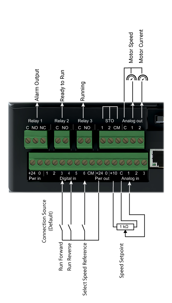
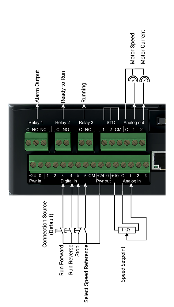
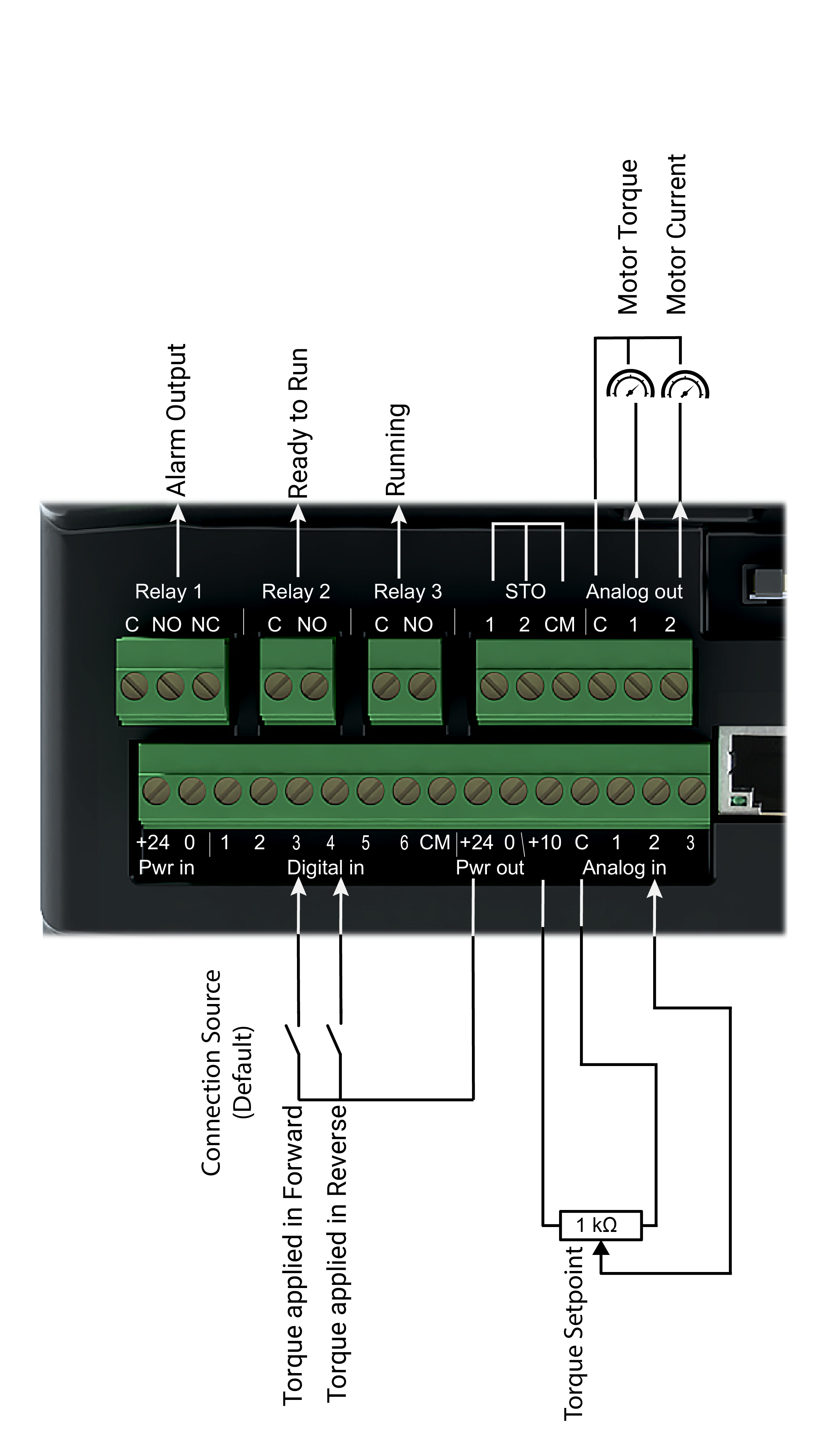
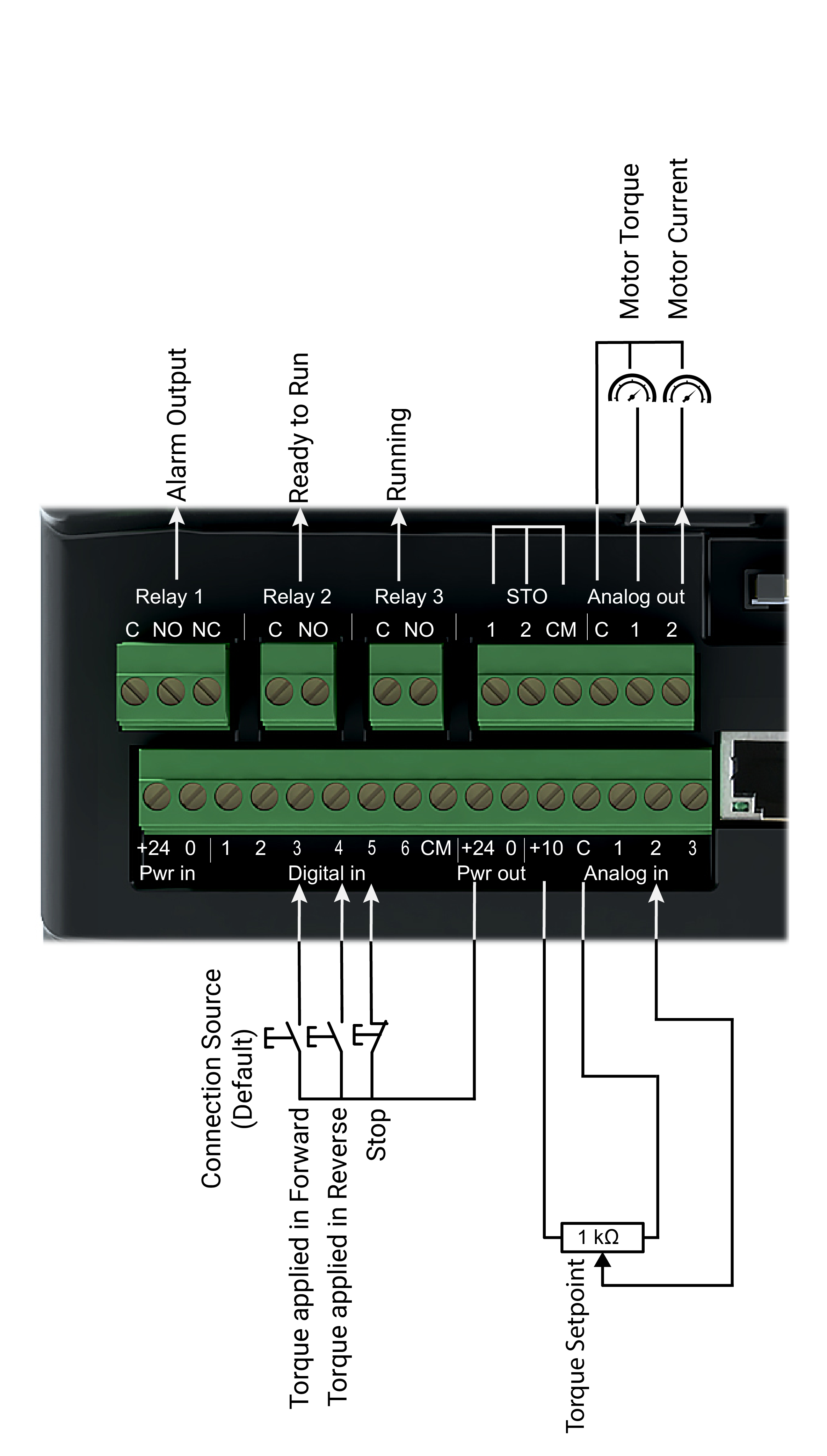
The following drawings show the I/O's that are used in the default presets with their function assignment. Those drawings are not wiring diagrams.
- Check the standard connection diagram section for the wiring.
- Check the control circuit description section for the attributes and values of the control terminals,
- and check the digital input logic connection section for the details of Source and Sink logic connection modes.
Wiring presets are available for speed control mode and torque control mode, with some slight differences in I/O assignment.
| I/O | 2- wires preset | 3-wires preset | ||
|---|---|---|---|---|
| Speed control | Torque control | Speed control | Torque control | |
| Di 3 | run forward | torque applied in the forward direction | run forward | torque applied in the forward direction |
| Di 4 | run reverse | torque applied in the reverse direction | run reverse | torque applied in the reverse direction |
| Di5 | stop | stop | ||
| Di 6 | select speed reference (if a preset speed is defined) | select speed reference (if a preset speed is defined) | ||
| Ai 1 | speed setpoint | speed setpoint | ||
| Ai 2 | torque setpoint | torque setpoint | ||
| Relay 1 | alarm output | alarm output | alarm output | alarm output |
| Relay 2 | ready to run | ready to run | ready to run | ready to run |
| Relay 3 | running | running | running | running |
| Aq 1 | motor speed | motor torque | motor speed | motor torque |
| Aq 2 | motor current | motor current | ||
2-wires connection for speed control:
3-wires connection for speed control :
2-wires connection for torque control:
3-wires connection for torque control :
For operation, read the chapters:
3-wires preset- Operation
and